

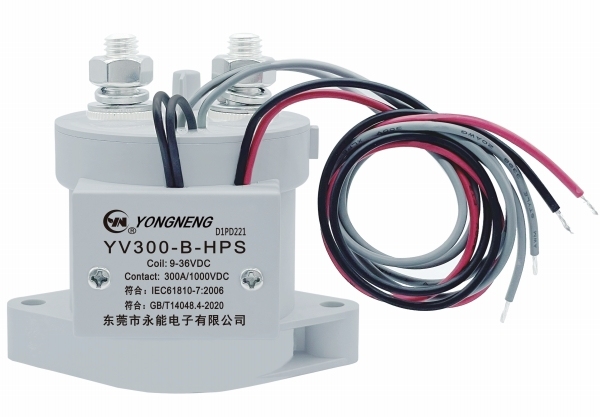
| Contact rating, resistive load | 300 A |
| Maximum switching current | 3000 A at 320 VDC |
| Maximum switching power | 960 kW |
| Coil rated voltage | 12 / 24 / 48 VDC |
| Coil lead-out | 300 mm as standard, other lengths on request |
| Auxiliary contact, maximum | 2 A at 30 VDC |
| Auxiliary contact, minimum | 100 mA at 8 VDC |
The steady rating is only half the story. Behind it sits a short-time ladder: the contacts are rated to carry 400 A for 120 minutes, 600 A for 20 minutes, 900 A for 30 seconds, 1200 A for 10 seconds and 1800 A for 0.6 seconds. That ladder is what a DC system actually asks for, because faults, inrush and pre-charge events push far more current through the bus than the running load ever does. Service life follows the same pattern. Mechanical endurance runs to 200,000 operations, while electrical endurance depends on what is being switched - 3000 operations at 300 A and 450 VDC, 1000 operations at 300 A and 750 VDC, and 500 operations at 160 A and 1000 VDC. Working near the top of the voltage range is entirely normal; plan a shorter service interval, or step up a frame in the same range if the duty never lets up.
| Insulation resistance, open contacts | 1000 MOhm at 1000 VDC |
| Insulation resistance, coil to contacts | 1000 MOhm at 1000 VDC |
| Dielectric strength, open contacts | 2500 VAC, 50/60 Hz, 1 minute |
| Dielectric strength, coil to contacts | 2500 VAC, 50/60 Hz, 1 minute |
| Unit weight, without auxiliary contact | Approx. 330 g |
| Unit weight, with auxiliary contact | Approx. 380 g |
YongNeng is a relay manufacturer supplying signal relays, latching relays and high-power relays, together with a high-voltage DC contactor line that runs from 16A up to 400A. Because our range covers everything from light switching duty to heavy DC loads, buyers can consolidate several switching positions with one supplier instead of sourcing each rating separately. Power relays are offered in sealed and open construction, and contact wiring is arranged for straightforward installation. Tell us the current rating, switching duty and mounting space your project needs, and we will help you match the right relay or contactor to your build.
| CONTACT DATA | |
| Model |
YV300 |
| Contact Arrangement |
1A |
| Contact Resistance |
<=0.5 mΩ |
| Current Withstand | 400A/120min,600A/20min ,900A/30S,1200A/10S,1800A/0.6S |
| Contact Rating ( Res.Load ) | 300A |
| Max. Switching Current | 3000A/320VDC |
| Rated load Voltage | 12-1000VDC |
| Max. Switching Power | 960KW |
| Mechanical endurance | 2x10⁵次 OPS |
| Electrical endurance | 3x10³次 OPS(300A 450VDC), 1x10³次OPS(300A 750VDC), 5x10²次OPS(160A 1000VDC) |
| Auxiliary Contact Data | |
|
Max.Current |
2A/30VDC |
|
Min.Current |
100mA/8VDC |
|
Contact Resistance |
<=100mΩ |
| CHARACTERISTICS | |
|
Rated Voltage(VDC) |
12/24/48 |
|
Action Time (ms) |
<=30 |
| Release Time (ms) | <=10 |
| Rebound Time(ms) | <=5 |
| Insulation Resistance | Between Open Contacts:1,000MΩ(1000VDC) Between Coil& Contacts:1,000MΩ(1000VDC) |
| Dielectric Strength | Between Open Contacts : 2,500VAC, 50/60Hz 1 min. |
| Between Coil & Contacts: 2,500VAC, 50/60Hz 1 min | |
| Coil End Lead Out Form | Leading 300mm / customized. |
| Ambient Temperature | -40℃~+85℃ ( No condensation) |
| Unit Weight | without auxiliary contact: Approx. 330g with auxiliary contact: Approx. 380g |
| Impact Stability | 196 m/s2 |
| Impact Strength | 490 m/s2 |


Match it to the current your circuit carries continuously, not to the largest number on the bus. Continuous current, the peak the system can deliver during a fault or inrush, bus voltage and switching frequency all feed into the choice. If your steady current sits comfortably below the rating with room left for those peaks, this is the right high voltage dc contactor for the job. Send the load profile and we will confirm the match.
Mount it on a flat, rigid surface so the body is not stressed when the main cables are tightened, and keep the main terminals facing the cable entry so the busbars do not have to bend sharply. Give the coil lead-out a clear route to the control terminals, and keep the unit away from heat sources such as braking resistors or transformer bodies inside the same enclosure.
Watch for heat building at the main terminals, a longer or louder arc on closing, and rising contact resistance measured across the main circuit during routine checks. Those are the usual signs that the contact faces have eroded past the point where switching behaviour stays stable. Compare the operations your panel has logged against the endurance figure for your load and voltage, and order the replacement before the unit reaches it.
It reports the state of the main contacts back to your controller, so the system confirms that the contactor has actually closed or opened instead of assuming it did. The auxiliary contact on this model has both a maximum and a minimum current rating, which matters when you drive a low-power input - an auxiliary that is too lightly loaded will not read reliably.
Think about where the device sits in the circuit. A general-purpose power relay handles control and signal switching on lower-power circuits. This is a high voltage dc relay built for the main power path: it closes against the full bus voltage, carries the load for long periods and opens under load, which is a far harder job on a DC bus than on a control line. Use it for battery buses, charger outputs and inverter feeds rather than logic-level switching.
There is no internal service to carry out - the contact chamber is sealed during assembly, so nothing inside is meant to be opened or cleaned. What you do check is external: terminal torque at your normal inspection interval, a dry terminal area free of conductive dust, and the coil leads for chafing. Where downtime is costly, keep a spare from the same relay supplier on the shelf.